“Ventilator”
Assisted
breathing machine
(Translated with www.DeepL.com/Translator)
Daniele Tommei - Digitarch Rome Italy
Rome April - 8 - 2020
The aim was to create a device of simple and economic production, with
basic characteristics and without ambitions of universal adaptability, but
which, although only in the simplest cases, can be useful. This machine, born
to help human beings with breathing difficulties, has been designed to be
easily built with low cost and easy to find components (the cost of all the
necessary parts just over 100 euros). It is necessary to specify, however, that
this machine is not a medical device and has not been certified for any of the
features listed below.
However, despite
the limitations set out above, given the practicality and simplicity of its
operation, we have made this document public so that those who wish to do so
can make it so that they can keep a device at home that they obviously hope
will never have to use.
In this document
and its annexes, all the information necessary for the construction of the fan
will be included, namely: the list of components and their availability, the
construction diagrams (mechanical, electrical and electronic) and the source
code of the software for programming the microprocessor used.
The operating
principle of this machine is based on the intermittent generation of ventilated
air to be inhaled through a nose/mouth mask worn by the patient.
Short video on stand-alone operation
Short movie about the operation in inspiration-controlled mode
(triggered)

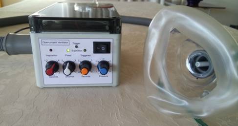
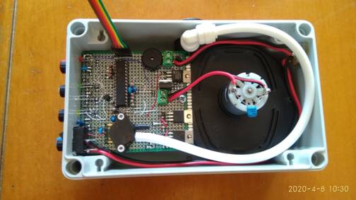
Composition of the
device for assisted ventilation:
The main parts of
this device are:
1) a high-pressure
centrifugal fan
2) a differential
pressure sensor
3. a microprocessor
electronic card
4) a parameter
settings panel
5) a container for
general applications
6) a power supply
adapter
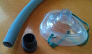
7) a flexible hose
with nose/mouth mask
Description of respiratory ventilator operation
A physiological human
breathing cycle consists of these three phases
-
inhalation
(approx. 1.3-1.5 seconds duration)
-
exhalation
(approx. 2.5-3 seconds duration)
-
short pause between exhalation and inhalation (approx.
0.5 seconds)
The natural action
of inhalation occurs through the enlargement of the chest cavity obtained through
the action of the different inspiratory muscles.
In case the patient
has difficulty in activating the inspiratory muscles to enlarge the costal arch
and thus expand the volume of the lungs to inhale the air, the respiratory
ventilator can help by directly introducing the air into the lungs, determining
the expansion and thus lightening the load on the inspiratory muscles.
This intake of air
must be synchronized with the first spontaneous muscle movement of inspiration
by the patient.
Specifically, the
mechanism of operation is as follows:
As soon as the
patient tries to breath in, a depression, albeit minimal, is generated in the
lungs, which is detected by the pressure sensor in the mask. The signal
detected by the sensor is transmitted to the ventilation device which
immediately generates the pressurized air that is injected into the lungs. Once
the air supply phase is complete, the ventilator stops and the patient can
automatically exhale air from the lungs in the following seconds. In this
second phase it is the lungs themselves which, without any muscular aid by
virtue only of their elasticity, expel the air contained in them.
At the end of the
exhalation phase, the natural breathing cycle starts again and with it also the
action of the ventilator. With this system, the air is introduced into the
lungs synchronously following the patient's natural breathing cycle.
The ventilator will
work even if the patient does not have the ability to begin the inhalation
phase independently. In fact, the ventilator is equipped with a timer that will
make it operate in any case, i.e. even if no inhalation attempt signal is
detected. In this hypothesis, the ventilator will still supply air into the
lungs after the period set in the timer has elapsed.
This concerns the
operation of the fan with detection mode activated. However, it is possible to
set the fan to autonomous mode.
In this mode, the
ventilator will introduce air into the lungs at regular intervals, regardless
of whether or not the sensor detects signs that breathing has begun. Of course,
this mode will be used in extreme cases where the patient is not in a condition
to stimulate assisted breathing.
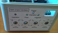
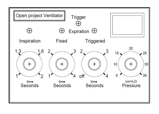
Control
panel: settings and indicators
On the front control panel there are four knobs, a switch, and four LED
indicator lights.
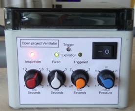
-
The red knob
(Inspiration) allows you to set the inspiration time. The adjustable value
ranges from 1 to 2 seconds and determines how long the ventilator will generate
the continuous flow of pressurized air to be sent to the patient's mask.
-
The red led above this knob indicates that the fan is
in action.
-
The white knob (Expiration Fixed) determines the
duration of the expiration period. The value can be set from 1 to 4 seconds and
during this period the ventilator will not produce airflow allowing the patient
to exhale the air contained in the lungs.
-
The green led above this knob indicates that the fan
is stopped and we are in the air exhalation phase.
-
The orange-colored knob (Expiration Triggered)
determines the maximum waiting period during which the ventilator is still
standing waiting for a patient's inspiration. As soon as the ventilator detects
an inhalation stimulus (red trigger LED) within this period, ventilation starts
immediately. If no inhalation stimulus occurs within the set period (can be set
up to 4 seconds) the ventilator will still start and a beep will sound to warn
the caregivers that the patient has not been able to inhale on his own.
-
If this orange knob is set to zero (off) the
ventilator will not wait for the inspiratory stimulus but after the previous
expiration phase (the green LED) the ventilator will start immediately.
-
- The yellow led above this knob indicates that the
fan is waiting for an inspiratory stimulus to activate the fan and generate
pressurized air.
-
The red Trigger LED sends a light signal when negative
air pressure is detected (patient attempt to inhale) during the
"Triggered" Expiration period set via the orange knob. If this knob
is set to "off" the Trigger led will not be activated.
-
The fourth knob, the blue knob (Pressure), determines
the maximum air pressure exiting the ventilator. The pressure value can be set
from 5 to 35 cm. of H2O (from 0.5 to 3.5 KPa).
-
The top right 0/1 switch controls the power on of the
device.
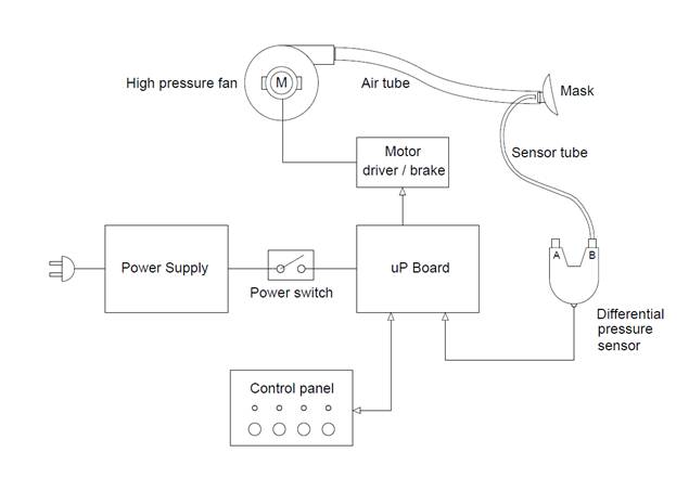
Description
of parts and operation diagram
This assisted
breathing device consists of these four main functional parts:
the fan, the pressure sensor, the microcomputer, the
control panel.
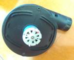
The
first of these is a high-pressure centrifugal fan.
This is driven by a
DC electric motor. The function of this fan is to suck air from outside,
pressurize it and send it through a hose to the mask worn by the patient. The
fan is called a high pressure fan because it produces significantly more
"pressurization" of the air than a normal fan.
The high pressure,
although not that high, must be at least about 20 cm. of H2O to ensure that it
is sufficient to "inflate the lungs".
To obtain this
characteristic, this type of fans have an impeller that rotates at a very high
speed, normally higher than 10,000 rpm and for this reason they must be well
constructed and balanced to minimize vibrations and noise produced.
In this project, at
the moment, the low cost has been privileged and therefore a very cheap fan (less
than 10 Euro) easily available because used in a common 12V inflator for
inflatable boats has been used. This
fan, in the test that we have carried out, comes to produce a pressure (with
zero flow) of 35 cmH2O. To obtain this
pressure, however, you need a 12V. power supply that can support at least 4A.
continuous (the one supplied does not exceed 2A.).
The impeller of
this fan can rotate at different speeds depending on the voltage applied to its
motor. Since the pressure of the air flow generated by the fan is a function of
the rotation speed, adjusting the electrical voltage on the motor will regulate
the air pressure generated.
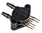
The
second functional part, of this breathing machine, is the pressure sensor.
Inside the air
transport tube, which goes from the fan to the mask, a second thinner tube has
been inserted to measure the pressure of the air sent. This small tube runs
along the entire length of the larger tube where the air passes, starting from
the fan and ending up at the plug on the mask.
While on the mask
side this small tube is left open and not connected to anything, on the fan
side it is connected to a differential pressure sensor.
The other input, of
the two inputs of the pressure sensor, is left open inside the box and not
connected to anything (actually it is not true that it is not connected to
anything: it has been left free just to measure the pressure inside the box).
This differential
sensor has the task of measuring the pressure difference between its two inputs
and transforming it into a signal that will indicate to the microcomputer what
is the difference in the air pressure value between the inside of the box
(which is actually the same as the ambient pressure) and the air inlet in the
mask.
It was considered
appropriate to extend the measuring tube up to the mask to improve the accuracy
of the air pressure measurement.
If in stationary
air conditions the pressure is always the same at every point of the tube, with
the air in motion there will be a pressure difference due to the pressure drop
between the beginning of the tube, connected to the fan, and the end of the
tube connected to the mask. In addition, the proximity of the measurement point
to the patient's mouth/nose improves the accuracy and speed of the ventilator's
response to the patient's inhalation attempt.
The differential pressure sensor has two functions:
-
The first function is to measure the positive pressure
of the pressurized air generated by the fan during the patient's inhalation
phase, which must remain within the limits set on the control panel. In this
phase the microcomputer will adjust the speed of the fan impeller to not exceed
these limits.
-
the second function is to detect the first inhalation
stimulus immediately after the exhalation phase. In a certain period of time,
which can be set from the control panel, the sensor will detect if there is a
rapid drop in pressure, following the patient's inhalation stimulus, and the
microcomputer will then immediately activate the generation of pressurized air
to help the patient to inhale.
The sensor used is
the MPX5010DP model available from RS-Components or other distributors of
electronic components, and has a flow rate up to 10KPa, i.e. 100 cm. of H20,
more than enough for the pressures in play that should never exceed 3.5KPa.
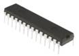
The
third functional part is the microcomputer.
A Pic16F series
micro from Microchip was used for this device. The model chosen is the 16f1718
in DIP version, which already has inside it all the functional modules needed
for this assisted breathing device such as CLOCK, ROM, RAM, ADC, PWM, etc..
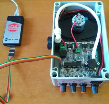
The microcomputer
can be programmed from any PC through a special interface such as PICKIT3 or
PICKIT4. The development system is MPLABX and can be downloaded free of charge
from the Microchip website. The program has been written directly in machine
code (MASM) and is documented among the attachments.
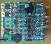
The microprocessor
is mounted on a prototype circuit board and does not currently have a dedicated
PCB. On the board together with the micro, all other electronic components
necessary for operation are assembled, as shown in the attached wiring
diagram. For the 12V. power supply of
the circuit, the same mains adapter supplied with the inflator has been used,
but of course it is advisable to purchase a more robust one such as the one
indicated in the list of the main parts needed.
It would also be advisable to connect a 12V. buffer battery of at least
10Ah, or alternatively use an uninterruptible power supply for computer to
ensure operation even in the event of a power failure.
The
fourth and last functional part is the control panel.
The panel simply
consists of 4 knobs and 4 LEDs, in addition to the power switch and a buzzer
inside the box.
At the moment we
have decided to keep to a minimum all the possible options and variables that
can be used to adapt the device to more particular cases, favouring simplicity
and easy management even by a home healthcare service.
The 4 knobs
regulate 4 different potentiometers connected to the microcomputer and set the
necessary parameters for the desired operation. The 4 leds, and the acoustic
signaller, also connected to the microcomputer, signal the different states of
operation to help and monitor the correct adjustment of the parameters.
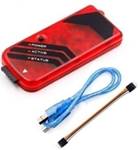
List of main parts
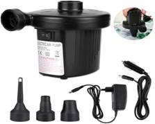
High pressure inflator, complete with 12V 2A adapter
https://www.amazon.it/gp/product/B07QQXV74M
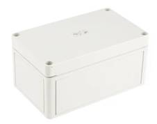
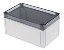
A plastic container
(180x110x90)
https://it.rs-online.com/web/p/contenitori-per-applicazioni-generiche/0832649/
https://it.rs-online.com/web/p/contenitori-per-applicazioni-generiche/0220440/
-
Microprocessor
Microchip Pic 16F1718 (DIL 28 pin)
https://it.rs-online.com/web/p/microcontroller/8417541/
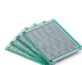
pcb for prototypes
https://www.amazon.it/ELEGOO-Millefori-Prototipo-Circuito-Prototype/dp/B073WR78M6
-
Pressure
differential sensor NXP mod. MPX5010DP
https://it.rs-online.com/web/p/sensori-di-pressione/7191080/
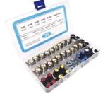
-
Potentiometers
and knobs
https://www.amazon.it/GTIWUNG-Potenziometro-Rotativo-Regolabile-3-Terminale/dp/B07WQG1RNZ
-
Programmer
for Microchip microprocessor
https://www.amazon.it/ARCELI-PICKIT3-Simulator-Programmer-Emulator/dp/B07BP65KQD/
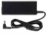
-
Power
supply 12 V. 7.5A
https://www.amazon.it/Caricabatteria-Adattatore-Alimentatore-Pico-PSU-Connettore/dp/B07588717M/
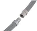
-
Washing
machine extension hose
https://www.amazon.it/Xavax-HAMA-Prolunga-scarico-metri/dp/B003ZYRN1M/
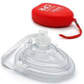
-
Mask
https://www.amazon.it/gp/product/B00P3YRRMC
Mechanical construction
To separate the fan
from the inflator, simply remove the two screws on the rear cover. Then we
desolder the electrical connections. From the inflator we also recover the
switch and the power connector.
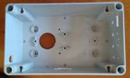
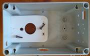
The box we used is
very small but still allowed to contain everything you need. Of course it is
possible to use larger ones.
After drilling the
box both at the bottom and at the side with a 31 mm diameter cup drill, we
shape and drill a rectangle of 6-8 mm thick pvc forex to fix it at the bottom
of the box.
With the help of
the attached template we can drill the holes on the front for the
potentiometers, the LEDs and the on/off switch
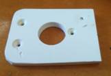
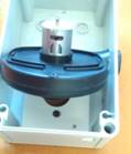
At this point we
can try to insert the fan and adapt the slots if necessary
We assemble the
electronic circuit adapting the size of the multi-hole PCB and solder the
potentiometers on the bottom side and the LEDs and the rest of the components
on the top side
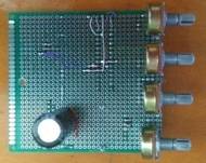
The circuit shown
is the prototype and therefore the connections have been made with wires
The board will be
fixed on the front side of the box by the same potentiometers.
On the back edge,
the card has been fixed directly to the fan through one of the holes already
present on the fan.
On the rear edge of
the box the power connector has been inserted, while on the front side the
On/Off switch has been inserted (both taken from the inflator).
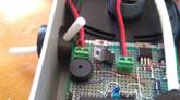
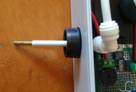
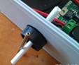
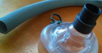
A 6 mm hole has
been drilled in the outlet of the fan, into which a tube of a few centimetres
is inserted as shown. This is the pressure sensor that will be brought up to
the mask. On the inside of the box the small tube, through a 90° connection,
will be connected to the pressure sensor on the side indicated, corresponding
to pin 6 (the other inlet must be left open). On the external side of the box,
a metal tube is inserted into the control line, which will be the connection
with the rest of the control line that will go to the mask.
The small tube,
passing inside the main 30 mm air tube, will come close to the mask worn by the
patient. In this way, the measured pressure will be exactly the pressure that
is inhaled by the patient. In addition, the time required to detect the
pressure drop induced by the inhalation attempt and thus the subsequent start
of the ventilator is reduced to a minimum.
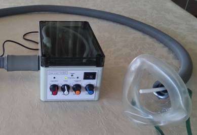
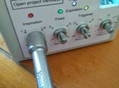
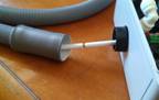
The air hose
connected to the respirator is connected to the fan using a piece of common PVC
hydraulic hose and heated to widen the internal diameter to about 30.5 mm.
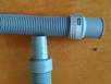


At the other end of
the pipe, the connection with the template is obtained by means of a fitting.
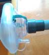
A second inlet can
also be seen on the mask to which the oxygen tube to the cylinder or to an
oxygen concentration machine can optionally be applied if necessary.
Technical notes on future
features and improvements
The heart of this device is the pressurized air
generation system. A small fan with DC brush motor has been used in this
machine to perform this function. This choice was dictated mainly by the easy
availability and low cost, but of course at the expense of the features. The
critical points of this type of fan are the noise, the not very high pressure
and the inertia in reaching the necessary rotation speed, which results in a
delay in the generation of pressurized air from the moment the demand is activated.
We have tried different types of commercial fans and
are testing others. The best choice will be to use a fan with a small impeller,
but with very high speeds above 30,000 rpm. Fans of this type use a brushless
motor. Unfortunately these fans, besides
being more difficult to find, are more expensive and require additional circuit
complexity for their operation. The model that could be a perfect replacement
for the current fan is the WM7040 which can reach a pressure of more than 60
cmH2O. This model, equipped with its driver board, can be easily inserted into
the current circuit, using the PWM signal that currently arrives at the gate of
the power mosfet IRLZ44 as a speed control.
The programming software
for the microprocessor has been developed on the MPLABX platform of the
Microchip (downloadable free of charge from their website) using a personal
computer with Windows. The control
program for the uP was written directly in the microchip's native code. For the
programming then a five-pole cable is used that directly accesses the micro via
a connector on the board. We used the PICKIT4 programmer but any other
programming system compatible with this uP family can be used. All source code
is included in the attachments of this project.
The code is not
very complex and can be easily modified to suit different needs.
Below is the
flowchart that summarizes the control mechanism of the uP. on the
interconnected hardware.
Description
of electrical operation
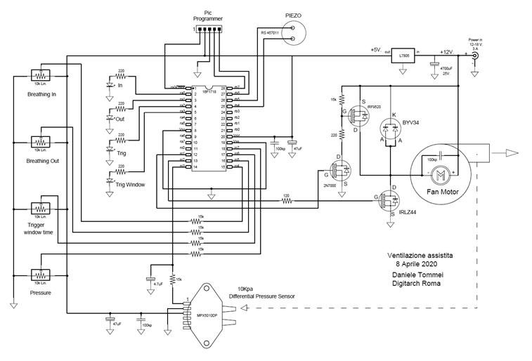
The circuit is
based on an in-line programmable microchip uP with internal clock set at 16
Mhz. The control circuit consists of 4 optical signalling leds and 4
potentiometers that provide 4 values from 0 to 5V. on the inputs of the uP and
a piezo acoustic signaller.
The power supply is
predisposed for a voltage of 12V. for an absorption of about 4 amperes of
current. The voltage of the logic part is 5V. and is generated by a linear
stabilizer L7805.
The fan speed is
controlled by the IRLZ44 N channel mosfet which is directly driven on the gate
by an output of the uP 16F1718. The current of this output is sufficient to
guarantee a switching time of less than 2 uS, short enough to use a PWM signal
with a cycle of 250 uS (4 Khz.)
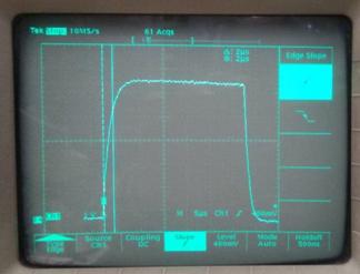
IRLZ44 Mosfet Gate signal
In parallel to the
motor a fast BYV34 diode is used as "freewheeling" for current
recovery. Also in parallel to the motor a P channel mosfet has been used to
short circuit and brake the motor itself, reducing the deceleration phase time
when the fan must be stopped quickly.
The MPX5010
differential pressure sensor produces a ratiometric voltage ranging from 0 to
the supply voltage (5V.) depending on the pressure difference between the two
pneumatic inputs. With an equal pressure on the two inputs the output voltage is
about 0.5V while with a difference of 10KPa (100 cmH2O) the voltage is about
4.5V It should be noted that the sensor can detect even a slight negative
pressure bringing the 0.5V output up to 0V.
The sensor is
connected through a small tube to the fan outlet in order to measure the
pressure in reference to the ambient pressure, detected by the second sensor
input left free.
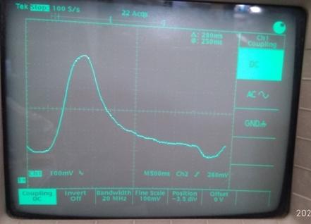
Pressure value on the sensor output
In the image above we can identify the air intake phase (steep climb)
and the exhalation phase (asymptotic descent) followed finally by the negative
pressure trigger phase.
All attached documentation (in
English) can be found here:
For information, suggestions
or other requests you can email to:
home page:
http://digitarch.net/Ventilator.htm